We offer comprehensive services for the evaluation of PV modules and their components. We support you in independent incoming goods inspection and evaluation of new module concepts using established standard tests and individual test sequences. We assist in the assessment of failure patterns and estimation of future development in use.
PV Module and Component Characterization
PV Module Characterization

Visual conspicuities are often the reason for more in-depth investigations. Some, such as cracks in the back foil, can have far-reaching consequences for the safe operation of equipment.

The electrical power under standard test conditions (STC) is an essential characteristic value of PV modules.

With the innovative method of magnetic field measurement, electronic components can be examined non-destructively for faults such as cable breakage or incorrect current direction.
- Visual inspection (e.g. delamination and cracking)
- Power measurement of solar modules
- Electroluminescence
- Magnetic field measurement
- Thermography
- Safety relevant insulation tests according to IEC and VDE-SPEC
- Peel test
Equipment
- Power measurement
- Berger Lichttechnik, solar simulator, class AAA, max. 2.6 x 2.2 m² | 10 ms flash
- WaveLabs LED solar simulator 2100, max. 2 x 1 m² | 500 ms flash
- HALM, solar simulator, class A+A+A+, max. 2.6 x 1.4 m² | 120 ms flash (in procurement
- Berger Lichttechnik, solar simulator, class AAA, max. 2.6 x 2.2 m² | 10 ms flash
- Electroluminescence measuring station
- greateyes, LumiSolarProfessional | max. module size: 2.5 x 1.4 m²
- CCD camera 2,048 x 512 px, stripwise recording of the module
- greateyes, LumiSolarProfessional | max. module size: 2.5 x 1.4 m²
- Magnetic field module measuring station
- DenkWeit, B-Lab, max. 2.5 x 1.4 m² | integrated in EL measuring station
- measurement of magnetic flux density in the module with current from 1 to 25 A (measurement from the front)
- adaptations for small samples and specimens
- DenkWeit, B-Lab, max. 2.5 x 1.4 m² | integrated in EL measuring station
Weathering and Accelerated Aging Tests

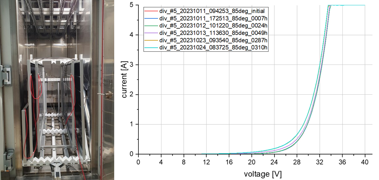
PID testing with customized dark curve measurement.

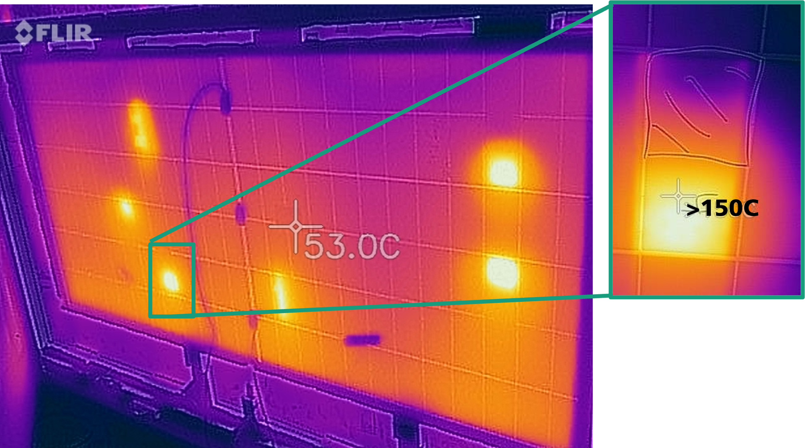
Hot-Spot-Test.
- Potential-induced degradation tests (PID) according to IEC TS 62804-series and IEC 61215-2 MQT 21
- LID / LETID test - stabilization and light treatment according to IEC 61215-2 MQT 19
- UV irradiation test according to IEC 61215-2 MQT 10
- Thermal cycling test (-40°C / 85°C) according to IEC 61215-2 MQT 11
- Humidity frost test according to IEC 61215-2 MQT 12
- Humidity-heat test (85°C/85%r.h.) according to IEC 61215-2 MQT 13
- Static and cyclic mechanical load test according to IEC 61215-2 MQT 16 / MQT 20
- Partial shading and hot-spot tests, among others, according to IEC 61215-2 MQT 09
- Combined UV-humidity-heat test
- Diode tests a. o. IEC 61215-2 MQT 18
- Customized test scenarios according to customer requirements
- Outdoor weathering and yield analysis

Mechanical load test for test specimens with a size of up to 2.3 x 1.5 m².

Climatic test chamber (46 m³, -60…+100°C, 10…90% relative humidity) with sun simulator radiation unit AM1.5 with 1000 W/m² for an exposure area of up to 6 square meters.

Climate test cabinet.
Equipment
- Climate test chambers
- CTS climatic test chamber C -65/100 | 2 units, 100 l, -65°C to 180°C
- CTS climatic test chamber C -70/200 | 2 units, 200 l, -70°C to 180°C
- CTS climatic test chamber C -70/1500 | 1500 l, -70°C to 180°C, 220 W/m² UVA/UVB irradiation
- Damp-Heat chambers, CW+40/8/8 | 3 chambers, 8 m³, 40°C to 90°C, 10 to 90 % relative humidity
- Walk-in climatic chamber, CWL -60/46 | 46 m³, -60°C to 100°C, 10 to 90 % relative humidity
- Walk-in climatic chamber, CW -60/23 | 23 m³, -60°C to 120°C, 10 to 90 % relative humidity, power supplies for current and continuity testing
- CTS climatic test chamber C -65/100 | 2 units, 100 l, -65°C to 180°C
- Irradiation chambers
- Atonometrics, LightSoaker | 2x 1.7 x 2.2 m² test area, sun-like spectrum
- Atonometrics, High Intensity UV | 2x 1.7 x 2.2 m² test area, excessive UV up to 200 W/m² UVA/UVB, metal halide lamps
- PSE UV chamber | 2x 2.6 x 1.4 m² test area, excessive UV up to 250 W/m² UVA/UVB, mercury vapor lamps
- Atonometrics, LightSoaker | 2x 1.7 x 2.2 m² test area, sun-like spectrum
- High voltage power supplies up to 6 kV and test benches in combination with climatic chambers for testing potential-induced degradation of modules and samples
- Pneumatic load test station, Harrexco, modules up to 2.2 x 1.5 m² with area load up to 8 kN/m² and multilocal deformation measurement
- Electrical safety
- Chauvin Arnoux C.A. 5550
- Wet leakage test (IEC 61215-2 MQT 15)
- Insulation test (IEC 61215-2 MQT 3)
- Ground continuity test (MST 13, IEC 61730)
- Reverse current overload test (MST 26, IEC 61730)
- Chauvin Arnoux C.A. 5550
Component Testing

Tensile test for characterization of frame material.

On the basis of specific experiments, the fatigue behavior of solar cell connectors can be simulated under varying mechanical and thermomechanical loads.

Test site for the mechanical loading of PV laminates with simultaneous electroluminescence (EL + 4PB).
- Determination of material parameters (e.g. Young's modulus, transverse contraction, yield stress)
- Strength assessment of solar glass according to DIN 1288
- Testing the strength of wafers and solar cells in accordance with DIN SPEC 91351:2017-04
- Strength assessment and crack investigation of encapsulated solar cells
- Fatigue strength evaluation of solar cell connectors
- Evaluation of substructures and mounting systems
- Testing of micro inverters
- Determination of degree of crosslinking using Soxleth and Xlink
- Polymer analytics
Equipment
- Precision Universal Testing Machines
- Zwick Roell GmbH, Z050 | static loads up to 50 kN, load cells 1kN, 10kN, 50kN tensile/compression test, flexure test, pull-off test
- Zwick Roell GmbH, Z400 | double ring and four-point bending test
- MTS Landmark 370.02, servo-hydraulic testing machine | static and dynamic loads up to 25 kN in a temperature range from -40°C to 350°C
- Instron 5848 Microtester | dynamic and static loads up to 2kN (10N, 100N, 2 kN loadcell), -40°C to 250°C
- Zwick Roell GmbH, Z050 | static loads up to 50 kN, load cells 1kN, 10kN, 50kN tensile/compression test, flexure test, pull-off test
- 3D image correlation system for spatially resolved measurement of local displacements
- Dantec Dynamic Q400, various calibration targets for measurements from µm to cm scale
 Fraunhofer Center for Silicon Photovoltaics CSP